
This manual contains information about Mobius features that were not covered in the Getting Started With Mobius manual. Among the topics will be customizing the user interface, advanced control options, projects, and track setups. It is required that you have at least skimmed Getting Started With Mobius .
The sections in this manual do not have to be read in any particular order, you can skim it and read only the sections that interest you. The Track Setups section is however highly recommended.
If you are interested in synchronizing Mobius with other hardware devices or applications, see the Mobius Synchronization manual.
For more detailed information on how to use some common Mobius functions see the Mobius Techniques manual.
A Track Setup is a named collection of parameters, presets, and controls for all tracks. It defines the initial state of all tracks before recording, and also defines the state each track will return to when it is reset. A setup stores the following things for each track:
In addition a setup contains the following parameters that apply to all tracks:
Finally, a setup contains synchronization parameters that apply to all tracks:
There is no requirement to define your own setups, Mobius comes with one default setup that you may be able to use without any changes. Setups are however very useful if you always want to change certain characteristics of a track before recording. For example, if you usually record with loud instruments you may want to reduce the input level from the default of 127 to avoid overloading the track. Rather than remembering to do this every time you start Mobius, you can set it in the setup and it will be automatically set to the desired level every time.
Another common use for track setups is to specify which physical inputs and outputs of a multi-channel audio interface to use for each track. By default Mobius always uses the first two channels as a stereo pair called a "port". But if your audio interface supports more than 2 input and output channels you may not want to use the first pair. For example with some audio interfaces the first pair of output channels may go to the headphone jack while the second pair of channels is connected to the monitor speakers. Mobius can't know which port is the correct one to use, you must select it in the track setup.
Setups are also useful if you need different track configurations for different compositions. If you play different instruments you may want different setups designed for each instrument. Or you may want to design a setup for a particular performance style like solo ambient looping and another for rhythmic "DJ" looping.
Finally, setups contain many parameters related to synchronization. If you wish to use synchronization other than Track Sync you will need to edit at least one setup.
To create and manage setups, open the Configuration menu and select the Track Setups item.
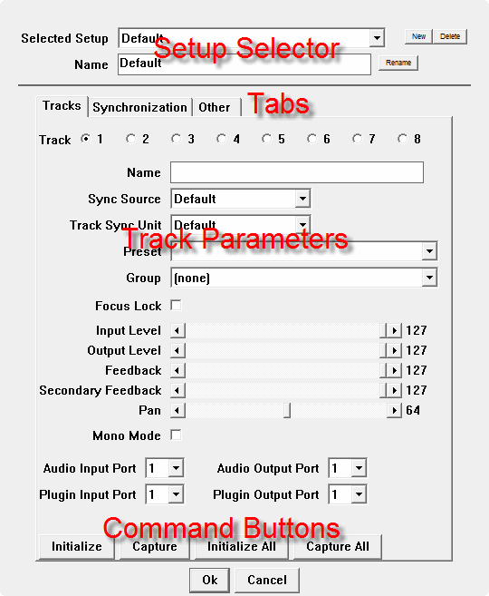
At the top of the setup window there is a collection of fields called the Setup Selector. These are use to select the setup you wish to edit, create new setups, and delete old setups.
Under the selector is a row of tabs to select different setup parameters. The first tab named Tracks has parameters that can be set differently for each track. The Synchronization tab contains parameters related to synchronizing tracks. The Other tab has a few additional parameters that apply to all tracks.
The Command Buttons at the bottom initialize the track parameters to their default values or to capture the track parameters from the current Mobius track.
Remember that after making changes in this window you must click the Ok button to save the changes.
The track parameters tab shows the initial state of each track. The values you enter here can be changed once you begin recording and working with tracks, but they will be restored to the values defined in the setup when you use the Global Reset function.
There are 8 sets of identical track parameters accessed with a radio button. To select the parameters for a track click on the small circle to the left of the track number.
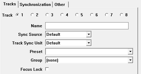
The Name field allows you to give each track an optional short name. When this is set the name will be displayed in the track strip instead of the track number. This can be used to help identify the purpose of the track, for example "drone", "rhythm", or "solo".
The Sync Source field defines the synchronization mode for this track. Each track may have a different synchronization mode, or they may all share the same mode. See the Synchronization Parameters of the Mobius Synchronization manual for more information about how to use this parameter.
The Track Sync Unit field defines the location in the loop where track sync will be performed. Each track may a different track sync unit, or they may all share the same unit. See the Synchronization Parameters of the Mobius Synchronization manual for more information about how to use this parameter.
The Preset field lets you set the starting preset for the track. You may for example want a preset that has quantization turned off for drone tracks, but turns quantization on for rhythm tracks.
The Group field allows you to set the initial track group for the track. The default is (none) which means the track is not a member of a group. Groups are identified by a letter, the number of available groups is set by the Max Track Groups parameter in the Global Parameters configuration window.
The Focus Lock checkbox determines if the track will start out having Focus Lock. This is an unusual thing to enable, but it may be useful if you want to begin by recording several tracks at the same time.
In the center of the track parameters tab, there is a group of sliders to set the initial values of all the track controls. These sliders correspond to the round knobs you see in the user interface.

The Mono Mode checkbox changes the track from stereo to mono. The track will still receive from a stereo input port and will send to a stereo output port. The difference is that the two input left and right input channels will be summed and recorded into both the left and right track channels. This may be useful if you are using an instrument that does produce a stereo signal. Connect the instrument to either the left or right input channel of the audio device. The instrument will be recorded into both the left and right channels of the track and then sent to both the left and right output channels of the audio device. The Pan control can be used to balance the levels of the left and right output channels.
At the bottom of the track parameters are a set of selectors for input and output ports. Each track must have both an input and an output port, the default for all is port number 1.

The Audio Input Port and Audio Output Port fields select the ports of the audio interface hardware to be used when Mobius is running standalone. The number of ports is determined by your audio interface. Ports correspond to a stereo pair of channels on the audio interface. If for example your audio interface has 8 input jacks, there will be 4 input ports. Jacks 1 and 2 will be port 1, jacks 3 and 4 will be port 2 and so on. You will need to experiment with the port settings to determine which ports match the jacks on your audio interface.
The Plugin Input Port and Plugin Output Port fields select ports to be used when Mobius is running as a VST or Audio Units plugin. Each port corresponds to a stereo pair of "pins" on the plugin. By default the Mobius plugin has 16 input and output pins, or 8 input and output ports. Most plugin hosts will default to using the first input and output port. If the host supports plugins with more than one input and output port you will need to understand how to route signals into and out of the plugin pins in the host. Some hosts will display pins visually and allow you to draw lines to connect them. Other hosts may display pins as numbers in a menu.
Below the track parameters is a row of command buttons.

The Initialize button will set all of the parameters in the currently selected track tab to their initial values. Controls all go to 127, pan goes to 64, the ports go to 1, the name, preset, group, and focus lock fields are cleared. The Initialize All button will set all parameters in all tracks to their initial values.
The Capture button will copy the current values of all parameters from a Mobius track into the setup. The selected track tab in the setup defines which track is being captured. For example if track tab 2 is selected, the parameters from Mobius track 2 are copied to setup tab 2. Capture is useful if you want to experiment with track settings in real time until you find the ones you like, then you can capture them all at once into the setup.
The Capture All button will copy the current track parameters for all Mobius tracks into the setup.
Obviously you need to be careful using the Initialize All and Capture All buttons, you need to be sure you want to replace everything in the setup. If you click one of these by accident, click the Cancel button to close the setup without saving the changes.
The Synchronization tab contains many parameters related to track synchronization.
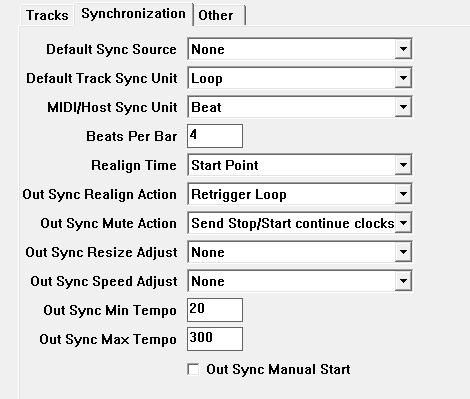
Synchronization is a complex topic that is described fully in the Mobius Synchronization manual. See the Synchronization Parameters for more information about how to use these parameters.
The Other tab contains a few miscellaneous parameters that apply to all tracks.
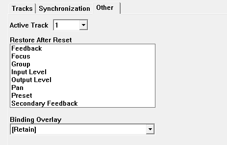
The Active Track field selects the track you want to be active when the setup is selected or after a global reset. Usually this is 1.
The Restore After Reset field is a multi-selection panel containing the names of some of the track parameters that are stored in the setup. Click on the names to highlight or unhighlight them. When one of these parameters is highlighted, its value will be restored to the value from the setup after the Reset or Track Reset functions are used.
All parameters in the setup are always restored whenever you use the Global Reset function to reset all tracks. But by default if you do a simple Reset to reset just one loop in a track, the parameters are not restored. This is because you may want to change input level, output level, or preset parameters while you are recording a loop. Then if you make a mistake and want to rerecord the loop you can use Reset to start over and none of your parameter changes will be lost. Some users however might always want the parameters from the setup restored whenever a Reset is performed. To accomplish that select some or all of the items in the Restore After Reset panel.
The Binding Overlay parameter determines which overlay binding set will be selected when this setup is selected. The default value is [Retain] which means to continue using whatever binding set is currently in effect. See the Multiple MIDI Binding Sets chapter of the Getting Started manual for more information on creating overlay binding sets.
The Binding Overlay selection menu will always contain the items [Retain] and [Cancel] and in addition the names of any defined MIDI binding sets other than the Common Bindings.

When [Cancel] is selected it means that the current overlay bindings will be canceled when this setup is selected. In the previous example the binding set Touch OSC Overlay was selected which means this binding set will be activated whenever this setup is selected.
The ability to control the overlay bindings is useful if you design a track setup with a particular piece of control hardware in mind.
If you tend to loop with the same instruments in the same style you may only need one default setup. But people frequently want more than one setup for different compositions or different performance environments. You may need several setups with the levels tweaked for different instruments. Or you may want different setups for home practice and live performance. You can create as many setups as you need and switch between them at any time.
At the top of the setup window is a set of fields and buttons that let you create, delete, select, and rename setups.

Mobius installs with one setup named "Default". To create a new setup click the New button. A new setup is created and selected. The new setup will have a copy of all the parameters from the setup that was selected when you clicked New. So if you want to create a setup that is similar to an existing setup, be sure to select the setup you want to copy before you click New.
When a new setup is created it will be given a generated unique name starting with "Setup" followed by a number. To change this name, click on the Name text field and type in the desired name, then click on the button labeled Rename. Simply typing in a name isn't enough you must also click the Rename button.
 |
| Renaming a new setup |
Once you have created several setups you can switch between them by using the Selected Setup menu at the top. Click on the down arrow to open a menu containing all the setup names. The setup that is selected in this menu will become the active setup when you click Ok to close this window. If you are making changes to several setups, be sure to remember to select the one you want to be active before closing the window.
 |
| Selecting a setup |
To delete a setup, simply select it and click the Delete button. The setup is deleted and removed from the selection menu. Be careful with the delete button, there is no "are you sure" prompt. If you delete a setup by accident, click Cancel at the bottom of the window to throw away the changes and open the window again.
After making changes that you are happy with, you must click the Ok button. If you click Cancel or the window close button all changes you have made will be lost.
When a setup is selected, all tracks that are currently empty will be modified to have the parameters defined in the setup. Tracks that are not empty will not be modified.
Another way to select setups is by using the Track Setups menu in the menu bar.
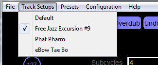 |
| Selecting a setup |
This menu will contain the names of all defined setups with a check next to the one that is active. To change setups simply select another one from the menu. If you just need to change setups without editing any parameter values using this menu is easier than opening the setup dialog.
A project is a collection of files that contain the complete state of Mobius at a moment in time, including the audio content of all loops in all tracks. You can use projects to capture a complex collection of loops that have just been improvised, or to define a set of background loops for a new performance.
To save a project, open the File menu and select the Save Project item. A standard file save dialog appears requesting you to select a Mobius project file. Navigate to the directory you want to use and enter a file name. Note that it may take several seconds to save the project. During that time do not use any Mobius functions, or change track controls or else these may be accidentally saved in the project.
A project actually consists of several files, a single project file with the .mob extension that you specify in the save file dialog window, and one or more .wav files containing audio content. If you have a complex collection of loops and tracks, there may be many files in a project. If so you may find it convenient to keep each project in a separate directory.
For example, assume we've saved a project named "myproject" that has two tracks, each with two loops. The project files that would be saved are:
  myproject.mob

  myproject-1-1-1.wav

  myproject-1-2-1.wav

  myproject-2-1-1.wav

  myproject-2-2-1.wav
The files containing audio are suffixed with three numbers. The first is the number of the track, the second is the number of the loop within the track, and the third is the number of the layer within the loop. Depending on how the loop was constructed, the layer number will usually be different than 1.
The project's .mob file contains the information necessary to reconstruct the Mobius state from all of the audio files. See the XML Files section for more information on the contents of this file. In addition to the files containing the audio content, the project's .mob file will contain the current state of all tracks including the track setup, the current presets being used, the current controller values (input, output, feedback, pan), the selected track number, and the loop number that is selected in each track.
By default only the most recent layer in each loop is saved. If the global parameter Save Project Layers is set, then a loop's entire layer history is also saved in the project. More than one .wav file will be saved for each loop. For example:
  myproject-1-1-3.wav

  myproject-1-1-2.wav

  myproject-1-1-1.wav
The third number in the file name is the layer number. These will be random numbers, though the most recent layer will usually have a higher number. Saving layers may be interesting if you use undo as a performance technique, and you want to start with a complex loop, then undo back to something simpler.
To enable saving the layer history, open the Configuration menu and select the Global Parameters item. Locate the parameter named Save Project Layers and check the box.
 |
NOTE: When you save a project with the same name as an existing project, all of the wave files in the existing project will be deleted first. This is necessary to avoid "garbage files" if you remove tracks or loops from the project. This will only occur however if the file is contained in the same directory as the project's .mob file. If you have manually edited the .mob file and added files a sample library, the sample library files will not be deleted as long as they are in a different directory than the .mob file.
To load a project, open the File menu and select the Open Project item. A standard open file dialog appears requesting you to select an existing Mobius project file. Navigate to the directory containing the .mob file, select it and click Open or Ok.
When you load a project, a Global Reset is performed, meaning that all of the current tracks and loops will be lost. After loading the audio content from the project all tracks will be placed in Pause mode, tracks will not begin playing automatically. You must now use the Pause or Play functions in each track to start them.
Mobius provides several options for saving and loading audio content to and from files. In this section we will discuss ways to save and load individual loops. You can also save and load projects which contain the audio content from all layers in all loops in all tracks. See the Projects section for more information on projects.
Load loading and saving is accomplished from the File menu:
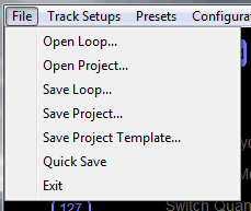 |
Mobius can only save and load audio content as wav files. The files may use either 16-bit integer samples or 32-bit floating point samples. Floating point is preferred because it has the best sound quality. When Mobius writes audio files it will by default use 32-bit floating point samples. If you have and audio application that cannot read floating point audio files, you can change the way audio files are saved with a global parameter.
Open the Configuration menu and select Global Parameters. In the popup window locate the 16 Bit Wave Files parameter.
 |
| 16 Bit Wave File Option |
Check the box next to the parameter name and click Ok to close the window. Now all Mobius audio files will be saved using 16-bit integer samples.
Note that this parameter does not effect how files are read. Mobius will continue to read both integer and floating point wave files.
NOTE: Mobius usually runs with a sample rate of 44100 or 48000. If you load files created outside of Mobius the files may use other sample rates but these will not be automatically converted to the Mobius sample rate. It is recommended that you only load files whose sample rate matches the Mobius rate. The example files that come with the Mobius installation were all created with a rate of 44100.
The Open Loop menu item is used to load a loop from a file into Mobius. Before loading a loop file you must first select the track and the loop in the Mobius main window that you want to replace with the contents of a file. Click on the track in the track strip, then use Next Loop or Previous Loop or the up and down arrow keys to select a loop. If you have the Empty Loop Action parameter set to Record in the preset, recording may begin automatically but it will be canceled during the load. Once the track and loop are selected, open the File menu and select the Open Loop item. A standard open file dialog will be displayed, navigate to the directory containing the file you want to load and select it. Mobius can only load wave files having the .wav extension. The file may be encoded using 16-bit integer or 32-bit floating point samples
The destination loop will be reset before the loop is loaded. After the loop is loaded, the track will be in Pause mode. The loop will begin playing from the beginning as soon as you use the Mute, Pause, or Play functions to cancel pause mode. In the default keyboard bindings the spacebar can be used to unpause the loop.
If you don't have any wave files handy, Mobius includes a few that you can experiment with. From the Open Loop dialog, navigate to the loops subdirectory of the Mobius installation directory. On windows this will normally be c:\Program Files\Mobius\loops, on Mac this will normally be /Applications/Mobius/loops. Select the file gcgroove.wav. Hit the spacebar and let the funk begin.
To save an individual loop, select the track and the loop you want to save, open down the File menu, and select the Save Loop item. A standard file save dialog will appear, navigate to the directory where you want to save the loop, and select or enter a file name.
The quick save feature allows you to save the current loop to a file without having to interact with a file save window. This is convenient if you create a loop you would like to remember, but don't want to put down your instrument and interact with the computer.
A quick save may be performed by opening down the File menu and selecting the Quick Save item. While you don't have to interact with a dialog window, you still have to select the menu item. A more interesting way to perform a quick save is by binding a button, key, or especially a MIDI event to the Save Loop function. You could for example bind Save Loop function to a button on a MIDI foot controller, then whenever you create something interesting just pounce on the button and the loop will be saved.
On Windows, the loop files are stored in the Mobius installation directory which is normally c:\Program Files\Mobius. On the Mac the loop files are stored in /Library/Application Support/Mobius. The files will have the name mobiusloop plus a number to make the name unique, for example mobiusloop1.wav, mobiusloop2.wav etc. Every time you perform the Save Loop function, a new unique file name is generated by adding one to the highest numbered mobiusloop file in the directory.
If you perform a quick save into a directory that already contains quick save files, Mobius will scan the directory to find the highest file number it must use in order to generate a unique file name. This ensures that a quick save will not overwrite an existing file made during an earlier Mobius session.
You may change the directory and base file name for quick save files by setting a global parameter. Open the Configuration menu and select the Global Parameters item. Locate the parameter named Quick Save File.
 |
If you want to change the base file name but keep the default directory, just enter a new name in this field.
 |
If you want to change the directory in which the files are stored you will need to enter the absolute path name of the directory and the base file name. On Windows this must begin with a drive letter, on Mac it must begin with a / character.
 |
If you are not familiar with absolute path names it is recommended that you let the files be saved in the default directory.
NOTE: Do not include the .wav extension to the file name, this will be added automatically.
The samples feature was designed primarily for testing Mobius, though anyone can use it. Samples are short audio recordings that can be loaded into Mobius and triggered with buttons, keys, or MIDI events. When triggered, a sample plays from beginning to end without interruption and then stops. If you trigger it again before the last sample playback finishes, another overlapping playback of the sample will start. Samples are not part of a loop or track, it is like having a very primitive built-in sample player.
So far this is pretty boring, but what makes samples interesting for testing is that while the sample is playing, the output is routed into the audio input of the tracks. So if the tracks are recording, they will record the samples you are playing, as well as whatever is coming in from the audio interface. This is convenient for testing because audio can be injected into the tracks just by pressing keys on the keyboard, without having to stop and play an instrument.
A sample is just an audio .wav file. To configure samples, open the Configuration menu and select the Samples item.
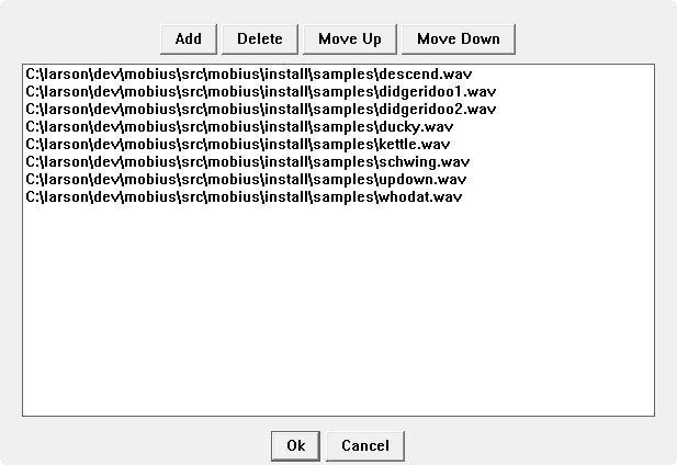 |
At the top of the samples window are buttons to add, delete, and reorder samples. The large panel in the center has the file names of the samples that are currently registered. To add a new sample, click the Add button. A standard open file dialog is displayed where you can select the .wav file to load. Added samples are placed at the end of the list. To delete a sample, click on the file name in the list so that it is highlighted then click the Delete button. To change the order of samples, click on a file so that it is highlighted then click the Move Up or Move Down buttons.
The order the sample files appear in the list is important because this determines which Mobius functions will trigger the samples. There are eight Mobius functions that will trigger samples. They all begin with the word "Sample" and are then followed by a number from 1 to 8, for example Sample1and ample2. The Sample1 function triggers the first sample in the list, the Sample2 function triggers the second sample in the list and so on. Because there are only eight sample trigger functions you should only register 8 sample files. You can add more but they will not be accessible.
To get a feel for how this works, Mobius comes with a small set of sample files you can try. On windows these are in the samples sub directory of the Mobius installation directory which is usually c:\Program Files\Mobius\samples. On the Mac these will be in /Applications/Mobius/samples.
Samples can be of any length though they are more useful if they are short. Because samples will "stack" if you trigger them several times rapidly you have to be careful about overloading the output bus and causing digital clipping. There is no way to adjust the level of the sample.
The Controlling Mobius section of Getting Started With Mobius described the process for creating bindings that let you control Mobius using devices such as a MIDI footswitch. In this section we will describe some advanced options that give you more precise control over individual tracks.
First a quick review of the concepts involved bindings. A trigger is an external stimulus that Mobius can receive and take action on. The most common example is a message sent from a MIDI footswitch. A target is something in Mobius that can respond to a trigger, examples include looping functions, track controls, and scripts. A binding is an association between a trigger and a target, for example binding MIDI Note 36 to the Record function means that the Record function will be executed whenever MIDI Note 36 is received.
Bindings are created using several popup dialog windows for each type of trigger. These binding windows are accessed from the Configuration menu items MIDI Control, Keyboard Control and Plugin Parameters. In addition you can create bindings for OSC messages but this is still an experimental feature that does not yet have a user interface.
One property of a binding that was not discussed in the Getting Started guide was the scope. Most users will use the default Global scope for their bindings which will target the currently selected track. But it is also possible to use scopes so that tracks are targeted even if they are not selected.
A binding may be given a scope to more precisely specify which targets are to be controlled by the trigger. There are many targets in Mobius because each track has its own independent set of targets. For example there isn't just one Output Level control target, there are eight, one for each track.
Functions may also have a binding scope. A trigger may for example do a Record in whatever the currently selected track is, or it may Record in track 4 all the time.
A binding scope menu is found in all of the popup windows that create bindings.
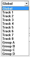 |
| Scope Selector |
When the scope is Global the binding is performed in currently selected track and all tracks that have focus lock. This is the most common binding scope.
The scopes Track 1 through Track 8 force the binding to be performed in a specific track no matter which is currently selected. This scope is particularly useful if you have a MIDI control surface with sliders and knobs that resemble a mixing console. A typical configuration is to bind a row of sliders to the output level controls in each track, and a row of knobs to the pan controls. Then you can mix and pan the tracks any time without worrying about which one is selected.
The scopes Group A through Group D force the binding to be performed on all tracks that are in one of the track groups. For this binding scope to be useful you must also assign tracks to groups, see the Track Groups section for more on how to use track groups.
When you create a binding using the default Global binding scope, triggers are sent to the currently selected track. This is the most common way to create bindings, rather than having 8 bindings for the Record function for each track, you just have one binding for the current track. Then you select the track you want to record by clicking on it in the Mobius window. This is similar to what computer operating systems call "input focus".
Occasionally though you might want to control more than one track at the same time without stopping to set up new bindings. For example you might want to mute or fade all tracks at the same time, send several tracks into reverse at the same time, or to begin a new loop recording simultaneously in several tracks. There are several ways to do this including scripts and Track Groups but the simplest way is to use focus lock.
Focus lock is a boolean track parameter that can turned on and off. When focus lock is on for a track, that track will receive all triggers that are bound to something in the global binding scope. For example assume focus lock is enabled in tracks 2 and 3 and track 1 is selected. If you trigger the Reverse function, tracks 1, 2, and 3 will all toggle their playback direction. Track 1 because it is selected, and tracks 2 and 3 because they have focus lock enabled. Similarly if you had a MIDI continuous control pedal with a global binding to the Output Level control, then moving this pedal will cause the output level in tracks 1, 2, and 3 to change at the same time.
Focus lock is rarely something that you leave on all the time, instead it is enabled temporarily only when you need control over multiple tracks. Because focus lock requires the performer to manually turn it on and off, it can be difficult to use during performance. Scripts are usually the preferred method for controlling multiple tracks, but focus lock is still available for simple things that don't require the complexity of a script.
If you are using the default user interface configuration, you can tell if a track has focus lock when the Track Number displays in a different color (usually red). In the next screenshot, you can see that track 2 is selected and track 1 has focus lock.
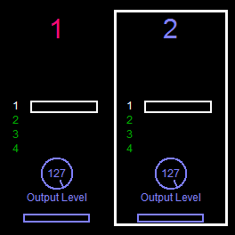 |
| Focus lock with the track number |
You can turn focus lock on and off by clicking on the track number. There is another component you can add to the track strip to control focus lock called appropriately Focus Lock. It is displayed as a small round button that is filled red when a track has focus lock. In the next screenshot, you can see again that track 2 is selected and track 1 has focus lock.
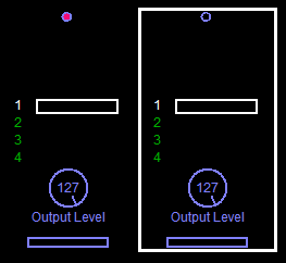 |
| Focus lock button |
You might choose to use the focus lock button if you want to save space in the track strip, though most people use the track number because it is easier to see and also helps you identify tracks. Like the track number, you can turn focus lock on and off by clicking inside the focus lock button.
During live performance it can be awkward for the performer to stop playing, grab the mouse, and click on focus lock buttons. Most people that use focus lock therefore use MIDI or the computer keyboard to set focus lock. The function named Focus Lock can be bound to any trigger. When executed it will toggle focus lock in the target track.
One approach is to bind the computer keys 1 through 8 to the Focus Lock function with the binding scope set to tracks 1 through 8. Then pressing the 1 key will toggle focus lock in track 1, pressing 2 will toggle focus lock in track 2, etc. Something similar could be done with a row of MIDI buttons on a footswitch or control surface.
Most functions can use focus locks, but a few special functions like Next Track or Track Copy do not. Generally any function that operates on a loop inside a track can use focus lock, but functions that operate on the tracks themselves do not. You may not want focus lock applied to all functions. For example you may want NextLoop, Restart, and Mute to obey focus lock but not Record and Overdub so you can control the recording of tracks individually but still mute them at the same time. You can control exactly which functions will obey focus lock by setting a global parameter. From the Configuration menu select the Global Parameters item. When the window opens select the Functions tab.
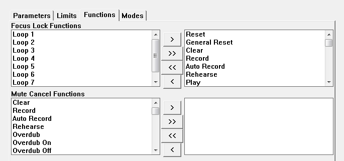 |
| Focus Lock Configuration Window |
This tab has two item selectors, the first one labeled Focus Lock Functions controls which functions will obey focus lock. By default most functions obey focus lock but the loop selection functions do not. If you do not want a particular function such as Record to obey focus lock, select it and remove it from the right panel. It does not matter what order the functions are in. When you have finished adding or removing functions remember to click "Ok" to close the window and save the changes.
A Track Group is used to organize several related tracks. By default there are four track groups defined in Mobius, and a track may be made a member of any one of those groups. Groups are identified by letters A,B,C,D but they may also be given user defined names in the Track Setup.
Assigning a track to a group does not by itself do anything very interesting. If you have the Group Name component enabled in the track strip you can see the group name which might help you remember how the tracks are supposed to be used. For example group A for percussion, group B for bass, and group C for solo.
Track groups become more useful when they are used as a binding scope. Recall that when you create a binding for a trigger such as a MIDI note, you can select a binding scope. The default binding scope is global which mean the trigger is sent to the currently selected track. If the binding scope is set to a group name, the trigger will be sent to all tracks in that group whether or not they are selected.
One example use for track group bindings is to bind a MIDI expression pedal to the output level control to the group whose tracks contain the percussion loops. Then with one expression pedal you can adjust the mix of all of the tracks at the same time. Using track groups in this way is similar to using Focus Lock but it is more flexible.
If you want to use track groups you will need to be able to see them in the user interface. In the default configuration, track group names are not visible. You will need to customize the track strip and add the item named Group Name.
 |
| Track Strip Item Selector |
You won't see much change initially because none of the tracks have been assigned to a group. The track strip will grow a little taller to make room for the group name but that space will be blank until the track is assigned to a group. Here is what the track strip will look like if you assign the first two tracks to group A and the second two to group B.
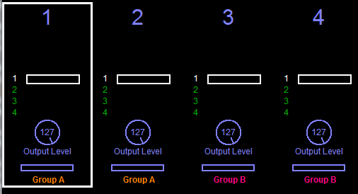 |
| Visible track group name |
Note that each group name is displayed in a different color to help identify them. You can change the colors by editing the color palette.
The primary way to assign tracks to a group is with a track setup. See the Track Setups section for complete information on how to define setups. In the setup parameters for each track is a group selector.
 |
| Group selector in the setup window |
In the previous example the first track has been added to the first group which by default is named "A". Whenever you change setups the displayed track groups will change to match what is defined in the setup. If you execute the Global Reset function, the current track groups will also be reset to match what is in the setup.
You may also change track groups in real-time by executing the Track Group function. Each time you execute the Track Group function the track is assigned to the next higher group. If the track is not currently assigned to a group it is assigned to group A. If the track is currently assigned to the highest group, the group membership is removed. The pattern is:
none, A, B, C, D, none, A, B, C, D, none...
If you have the Track Group function bound to a Sustainable Trigger and you do a long press of the trigger, the group assignment is removed.
You can also set track groups using scripts, this is described in detail in the Mobius Scripting manual.
If you find that 4 track group is more than you need, you can reduce the number using a global parameter. From the Configuration menu select Global Parameters, when the window opens select the Limits tab.
 |
| Changing the number of track groups |
Locate the parameter named Track Groups and enter the desired number. In this example the number has been changed from 4 to 2. Changing the number of track groups is primarily of interest if you want to use the Track Group function to cycle over the groups. If you only need two groups then this changes the Track Group pattern to:
none, A, B, none, A, B, none...
The Output Level control will behave in a special way if it is bound using a track group scope. The output level of the tracks in the group will be changed relative to their current output level, rather than all set to the same value. This allows you to set up a mix of several tracks with different output levels, then adjust the overall output level of the group "bus" without changing the mix of track levels.
For example, assume track 1 and 2 are in the same group and track 1 has an output level of 127 (the maximum) and track 2 has an output level of 100. Decreasing the output level by 10 using a group binding will lower the level of the first track to 117 and the second track to 90.
This special behavior is available only for the Output Level control and is canceled if you use any other level control such as a UI knob or a trigger that does not use the group binding scope.
Before release 1.43, track groups behaved like a more powerful version of Focus Lock. This is no longer the default behavior because it was confusing and made it harder to use bindings with group scope. If you would like to restore this old behavior open the Global Parameters window and check the checkbox labeled Groups have focus lock.
 |
| Activating group focus lock |
When this option is enabled any triggers that have bindings using global scope are sent to the currently selected track and all tracks that are in the same group as the selected track. For example assume that tracks 1, 2, and 3 are in the same group and track 3 is selected. The Reverse function has a global binding to a MIDI note. When this MIDI note is received, tracks 1 2 and 2 all change direction, 3 because it is selected and 1 and 2 because they are in the same group as 3.
Like simple focus lock, track group focus lock is only available for function bindings that use the Global binding scope. If you create a binding scoped to a specific track or track group, group focus will have no effect on that binding.
Also like simple focus lock, you may not want all functions to be sent to all tracks in the group. You can use the same global parameter described in Limiting Focus Lock to decide which functions should obey group focus lock.
The reason this is no longer the default behavior is because we have found that the ability to assign things like the Output Level control to a group is useful for mixing. But once you did that, all tracks in the group would respond to functions like Record at the same time which is not usually what you want. You can edit the Focus Lock Functions global parameter to remove all the functions you don't want to obey focus lock, but it's easy to forget. Most people never want a combination of both group bindings and group focus lock. So rather than making the combination the default we made the default to disable group focus lock and only support group bindings.
If this is confusing don't worry, it has always been hard to explain and few if any people have ever made good use of it. Just leave the Groups have focus lock checkbox off.
The Arguments text field in the bindings windows allows you to enter text that may control how the binding behaves. What you can enter here will depend on both the trigger and the target. Arguments may be used for all Control bindings and a few Parameter and Function bindings.
You normally use binding arguments only for "one shot" triggers such as a MIDI note, MIDI program change, or computer keyboard key. Bindings arguments when the trigger is a MIDI continuous controller are ignored.
Controls are usually bound to a MIDI device that can send continuous controller messages, such as a foot pedal, slider, or rotating knob on a control surface. This is necessary because controls have a range of values and MIDI CC messages allow you to sweep over all of the possible values.
If you bind a control to a trigger that doesn't support a range of values such as a MIDI note, the binding will have no effect. When we receive the note we don't know what value to give the control. This can be fixed by entering binding arguments.
Binding arguments for controls start with an operator and follow with an operand which is a number.
The available operators are:
min will set the target to its minimum value, max sets the maximum value, and center sets the center value. These three operators don't have an operand. These operators are normally used only when the target is a control.
up will increase the current value of the target by some amount, down will decrease the current value by some amount, and set will set the target to a fixed value. All of these require an number operand. These can be used when the target is a control or a parameter.
Here are some examples:
If you bind a pair of MIDI notes to a control and give one the arguments "up 1" and the other then arguments "down 1" you can sweep the control through the full range of values by repeatedly pressing the MIDI notes.
If you try to set a control to a value more than 127, it will be constrained to 127. Similarly if you try to set a control to a negative value if will be constrained to zero.
Binding arguments can be used with any parameter whose type is an enumeration meaning it has a fixed set of possible values, or is an integer meaning that it is a small number. Examples of parameters that you might want to use are Subcycles, Quantize Mode, and Switch Quantize.
For integer parameters, the binding argument may be a number within the allowed range of the parameter. For example, binding a trigger to the Subcycles parameter with an argument of 8 will force the number of subcycles to 8 whenever this trigger is received. Before we had binding arguments, operations like this were frequently done with scripts. By using binding arguments you can avoid scripting in these simple cases.
For enumeration parameters, the binding argument must be the name of the parameter value. This type of binding is a bit more complicated because you must use the internal script name of the parameter value. For example the Quantize Mode parameter has the following internal values: off, subcycle, cycle, loop. So to force the quantize mode to loop, create a binding and enter loop as the argument. You will need to consult the reference manual to understand the possible parameter values for each enumeration parameter.
A few functions also allow binding arguemnts. These include:
In most cases, the argument is a small positive or negative number, for the speed and pitch functions this number indiciates a change in semitones up or down. For example setting an argument of 7 for the Pitch Step function will cause the function to raise the pitch by a 5th.
Consult the reference manual for each function for more information on how it supports binding arguments.
If you are using the Mobius VST or AU plugin, another way to control it is through plugin parameters. The term "plugin parameter" must not be confused with Mobius calls a Parameter. Plugin parameters are used for communication between a VST or Audio Units plugin and the host application. Plugins typically declare a small number of parameters that the host can then display using a simple user interface with sliders and menus. Further the host may support "parameter automation" that allows you to draw value curves in a timeline and have the parameters change in real time. Finally hosts can often store the last known values for all of a plugin's parameters in a "session file" that may be restored later.
Plugin parameters are an advanced topic because what you can do with them depends greatly on the host application you are using. Here we will simply discuss how you cause targets in Mobius to be exposed as plugin parameters. For information on how to use these parameters with the various hosts you will have to check forum.
Mobius has literally hundreds of targets that could be exposed as plugin parameters. Because there are so many they are not all exposed by default, you must explicitly ask for the targets you want exposed. To define plugin parameters open the Configuration menu and select the Plugin Parameters item.
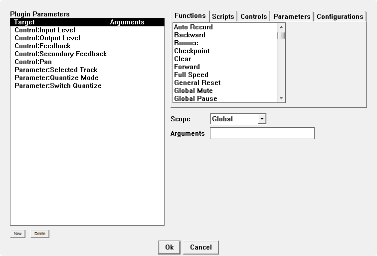 |
| Plugin Parameter Window with Default Parameters |
This looks like the other binding windows for MIDI and keyboard control. The unusual thing about parameter binding is that there are no fields for defining a trigger. This is because the association between a trigger and the plugin parameter is done in the host application rather than in Mobius. Mobius simply advertises a set of parameters that the host can use, the association of those parameters with things like MIDI events is done in the host.
The typical steps for defining plugin parameters are:
Plugin parameters can sometimes be used as sustainable triggers but it depends on the host application. The host needs to support the concept of a "momentary button" and set the parameter to non-zero when the button is pressed and zero when released. Not all hosts support this concept, some treat all parameters as continuous floating point values and display them as sliders rather than buttons.
It is possible to control every Mobius target using OSC messages. This is an advanced feature that is still under development. For more information see the Mobius and OSC manual.
MIDI Status Export is an option that will cause Mobius to send MIDI events whenever certain parameters or controls change. It is intended for use with bi-directional control surfaces that can both send MIDI to Mobius to change something and also receive MIDI to track changes made within Mobius. For example a control surface may have a rotary knob used to set the Mobius Output Level control. When you turn the knob the hardware sends MIDI messages to Mobius to change the output level. But if you then change the output level in the Mobius UI or from a script, the position of the hardware knob may no longer match the output level that is actually being used in Mobius. Some newer control surfaces support bi-directional communication which means that the application may send MIDI back to the hardware to make it change the position of knobs, sliders, or buttons.
When MIDI feedback is enabled in Mobius, it will send MIDI events whenever a parameter or control changes and those parameters or controls have a MIDI trigger binding. For example if the Output Level control has a binding to MIDI continuous controller 42, then whenever the output level is changed in the Mobius UI, continuous controller 42 events will be sent to the selected MIDI output devices. If a parameter or control does not have a MIDI binding then no MIDI messages will be sent.
There are two global parameters that control MIDI status export. The MIDI Status Export parameter will cause MIDI status events to be sent to the MIDI output devices selected in the MIDI Devices window. This is normally used only when running Mobius in standalone mode, but it can be used in the Mobius plugin if you are opening private MIDI devices.
The Host MIDI Status Export parameter will cause MIDI status events to be sent to the VST or Audio Units plugin host. This can only be used when Mobius is running as a plugin. If you use this option you must then route MIDI coming from the Mobius plugin to the hardware control surface in the host. Every host does this differently and some don't even recognize MIDI generated by a plugin. If your host does support routing MIDI from a plugin, that is the recommended approach. If it doesn't then you can configure Mobius to open a private MIDI output device when in plugin mode and set the MIDI Status Export parameter instead. But be careful because having Mobius open MIDI devices can cause conflicts with some hosts.
The user interface can be changed in many ways: buttons can be added to the button area, components can be added and rearranged in the status area, and components can be added and rearranged in the track strips. Most customizations are performed using a set of popup dialog windows accessed from the Configuration menu.
Note that it is often necessary to resize the Mobius window after adding or removing things from the UI. If you are running Mobius as an Audio Unit plugin, or as a VST plugin in "single window mode" you will not be able to resize the window. You will need to first run Mobius standalone to resize the window, then the new window size will be used by the plugin window the next time it is opened.
Many of the configuration windows use a set of buttons and panels collectively called an item selector. These will have different labels and contain different items but they all work the same way. Here is an example item selector from the Display Components window.
 |
| Example Item Selector |
The panel on the right contains the items that are currently selected. The panel on the left contains the items that are available for selection. In the center is a column of buttons that move items between the two panels. To select an item, click on the name in the left panel to highlight it, then click on the button labeled ">". To deselect an item, click on the name in the right panel, then click on the button labeled "<". The button labeled ">>" will move all items to the right panel and the button labeled "<<" will move all items to the left panel.
Note that if the list of items is long there may be a scroll bar on the right edge of either panel. If that is the case you will need to use the scroll bar to see all of the available or selected items.
For many item selectors, the order of the items in the right panel will determine the order the items are displayed in the user interface. If you want things to display in a certain order you will have to carefully select them in the desired order. You will quickly find out that drag-and-drop is not supported in the right panel so ordering the buttons can be tedious. It is best to plan your ordering ahead of time, use the "<<" button to clear the right panel, then add your items one at a time in the desired order.
The button area is a strip across the top of the Mobius main window containing clickable buttons to trigger functions and scripts.
 |
| Default Buttons |
To add or remove buttons in the button area, open the Button Configuration window by selecting the Buttons item from the Configuration menu.
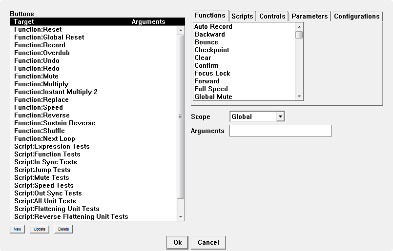 |
| Button Configuration Window |
The button configuration window looks similar to the other binding windows. The panel on the left lists all of the currently selected UI buttons, the upper right has panels for selecting a target for the button, and the middle right has selectors for the button scope and arguments.
To add a button, select a target, optionally set a scope, and click the New button under the button list. To delete a button, select it in the button list and click the Delete button under the button list.
Like other bindings, buttons can have arguments, see Binding Arguments for more on what can be done here. If you need to change the arguments of an existing button, select the button in the list, change the arguments, and click the Update button under the button list. You would normally only use targets of type Control or Parameter if the binding had arguments to set the new value for the control or parameter.
Note that if you add buttons the button area may grow. If one row of buttons becomes full, another row will be added and the status area will be shifted down to make room. Shifting the status area down may sometimes cause it to overlap the top of the track strip which can cause the components to draw incorrectly. If this happens you will need to resize the window and either make it taller to make room for the extra button row, or make it wider so that an extra button row is not required.
If you are using Mobius as a plugin you may not be able to resize the window. You will need to run Mobius standalone to resize the window, the new window size will then be used for the plugin windows.
The status area is the large area in the center of the window between the buttons at the top and the track strips along the bottom. This area contains many components that display the state of the selected track.
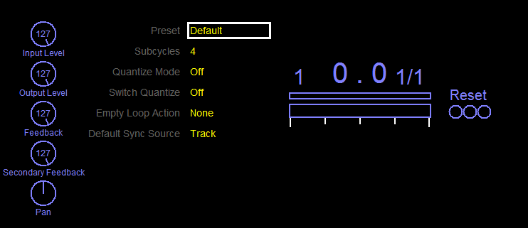 |
| Default status area at rest |
You can add or remove components and move them to new locations. Some components are initially invisible and will appear only when certain things happen in the track. To see the names and outlines of all active components, press and hold the Z key on the computer keyboard.
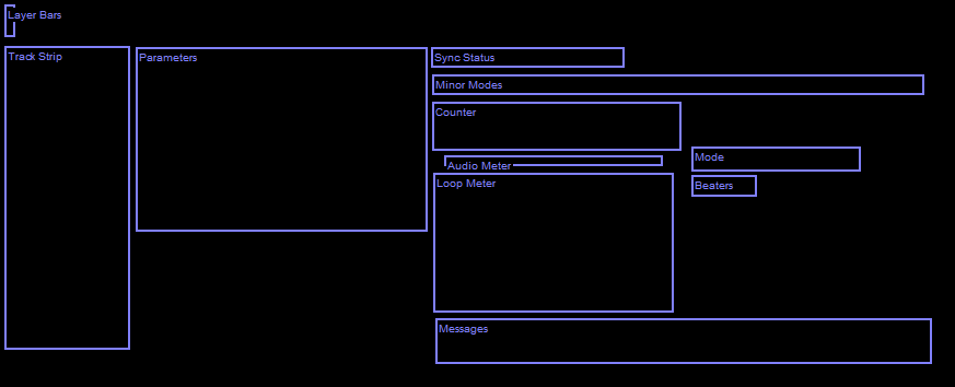 |
| Default status area component outlines |
Note that as you add or move components in the status area you may notice that some of the components are partially erased with a black rectangular area. This indicates that one or more components overlap. When this happens you need to use Z to switch to outline mode, and drag the components so that they no longer overlap. To drag a component in outline mode, click over it with the left mouse button, hold the button down, and move the mouse to a new location.
To configure components in the status area, open the Configuration menu and select the Display Components item.
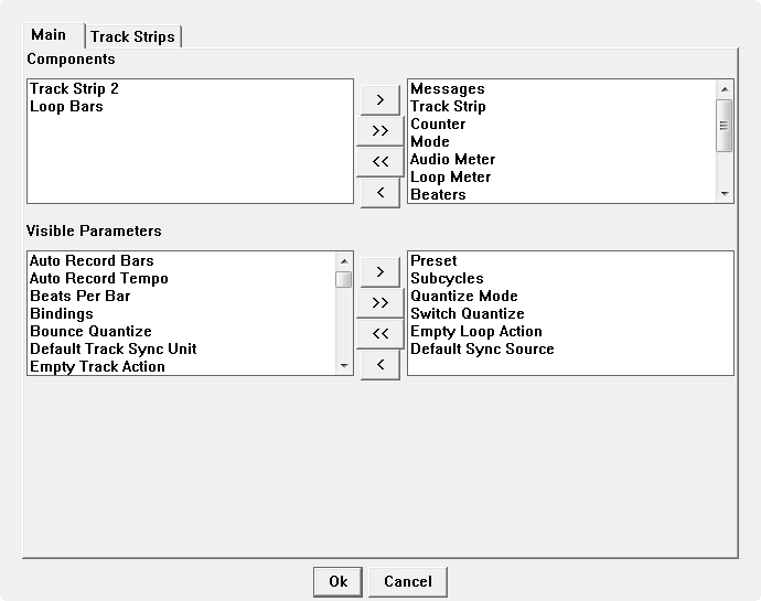 |
| Display Components Window - Main Tab |
The window has two tabs, one to select the components in the status area and another to select the components in the track strips. We'll start by exploring the first tab labeled Main. This tab contains two item selectors.
The first item selector is labeled Components and determines which components are displayed in the status area. See the Status Area section of Getting Started With Mobius for details on the purpose of each component and how it looks.
 |
| Status Area Components Selector |
By default, all status area components are selected except for Loop Bars and Track Strip 2. It is recommended that you do not remove display components until you have used Mobius for awhile and have a better understanding for the things you don't need.
The second item selector labeled Visible Parameters determines which preset parameters will be displayed in the Instant Parameters component.
 |
| Instant Parameters Selector |
Note that you will see this component in the status area only if you have Parameters selected in the Components item selector at the top of this window. The default instant parameter component looks like this.
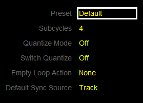 |
| Default Instant Parameters Component |
The parameters will be displayed in the order they appear in the right item selector panel. If you add parameters to this list the Instant Parameters component will become taller and may start overlapping with other components or with the track strip. You may need to resize the window to make it taller, or move the components so they do not overlap.
A Track Strip is a display component that can contain other components for controlling tracks and showing track status. There are two types of track strips you can configure, fixed track strips that are arranged along the bottom of the Mobius window, and floating track strips that may be added to the status area.
Each track has one fixed track strip arranged in a row along the bottom of the window. While you can change the components dispalyed in the fixed track strips, they will all have the same components and they cannot be moved. Usually the Track Number component is displayed so you can easily identify the track. Fixed track strips typically have components that show the track status such as the Loop Status list and the Loop Radar and may contain a few track controls such as Output Level. The next picture shows the default components in the fixed track strips. The currently selected track will have a white rectangle drawn around its track strip.
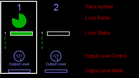 |
| Default fixed track strips |
The floating track strips are displayed in the status area, by default there is one on the left containing the major track controls.
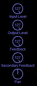 |
| Default primary floating track strip |
The components inside the track strips are always arranged horizontally. Because there are many controls and status components that can be added, it is possible to create track strips that are very tall. To keep the floating track strips shorter, there are two of them that may be added to the status area and they can contain different components. To add the secondary floating track strip to the status area, go to the Main tab of the Display Components window and move the item Track Strip 2 into the panel on the right.
 |
| Adding the secondary floating track strip |
The next picture shows the status area with both floating track strips. By default, the secondary track strip is positioned on the right side, but it can be moved.
 |
| Default secondary floating track strip |
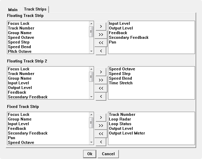
To change the components that are displayed in the track strips, go to the Track Strips tab of the Display Components window. The tab contains three item selectors, the first two select the components to be displayed in the two floating track strips, and the third selects the components to be displayed in the fixed track strips along the bottom.
 |
| Display Components Window - Track Strips Tab |
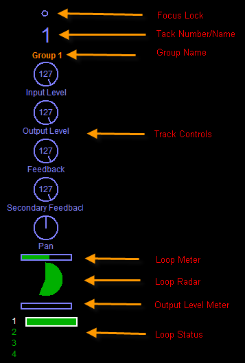
Like other item selectors the panel on the right shows which track strip components are selected and the order in which they will be displayed. The next screenshot shows what a track strip would look like if most of the possible items were selected and in the sections that follow we will describe each of the components.
 |
| Fully loaded track strip |
The Focus Lock component is similar to a small LED that will be lit when the track has Focus Lock. If you click on this component it will toggle the state of focus lock. It is not used often since the Track Number can also indicate which tracks have focus lock.
The Track Number component is a useful and popular choice for the track strip. It will display either the track number or a user defined track name from the setup. When the track has focus lock the number or name will be displayed in a different color. Clicking on the number or name will toggle focus lock, just like the Focus Lock component.
The Group Name component displays the name of the group assigned to this track. This component is only selected if you choose to make use of Track Groups.
The Track Controls are knobs that display and modify various track operating levels. See the Using Controls section in Getting Started With Mobius for information on the purpose of each of these controls. Each knob can be added or removed individually. Some of the newer controls related to speed, pitch, and time stretch are not shown in the previous screenshot but they may be added. Unlike other components in the track scripts, the track controls may be modified by the user. Click and hold the mouse button over the knob and drag the mouse to change the value.
The Loop Meter is a smaller version of the Loop Meter shown in the status area. It fills with color as the loop plays but it does not have subcycle markers or show scheduled events.
The Loop Radar is an alternative to the Loop Meter that is popular with many users. It displays progress through the loop as a pie-chart which is often lovingly referred to as the "loop pacman". When the loop is at its start point the radar will be empty, as the loop plays it will draw a clockwise filled arc. When the loop is at the end point it will display as a complete filled circle, then clear and start over. While this is larger than the Loop Meter it is easier to see from a distance.
The Output Level Meter is similar to the Audio Meter except that it shows the level of the audio signal being played in the loop. It is another "thermometer" that will bounce around according to the average loop level.
The Loop Status component is another useful and popular track strip component although it does consume a lot of space. Each row represents one loop in the current track. If the loop has content a green rectangle is drawn. The active loop will be drawn with a white border. If you are performing a Loop Switch , the next loop will be drawn with a red border.
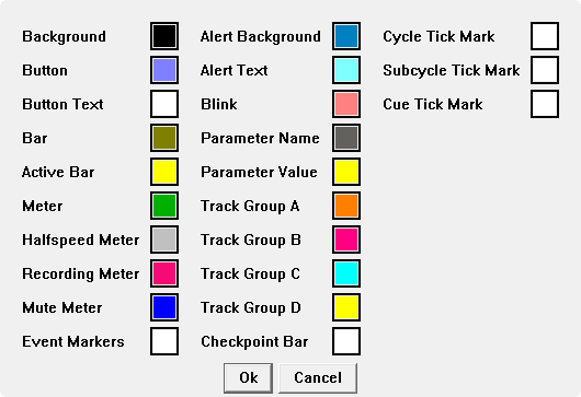
To change the colors used in the main Mobius window open the Configuration menu and select the Palette item.
 |
| Palette Window |
Some of the colors such as Cycle Tick Mark are used for very specific parts of the display. Others such as Button are used in many components. We won't document the exact meaning of all the colors but most of them should be self-explanatory. Experiment to see the effects of each color.
To change a color, click on the color box with the left mouse button, a standard system color dialog will pop up. Select a color and click Ok in the standard color dialog. When you are finished changing colors click Ok on the palette dialog and the color selections will be applied.
It is possible to change the fonts used in the main Mobius window but this is still considered to be an experimental feature that should only be attempted by advanced users. There is no user interface to change fonts, you must edit the UI configuration file in a text editor. If you are not comfortable editing XML files do not attempt this.
The UI configuration file is named ui.xml. On Windows this will be found in the installation directory which is usually C:\Program Files\Mobius 2. On OS X this will be in the directory /Library/Application Support/Mobius 2. Edit this file in a text editor, do not use a word processor to edit Mobius XML files. It is important that these files be saved as simple ASCII text. See the Using Scripts section of Getting Started With Mobius for details about how to properly edit text files for Mobius. Always make a backup copy of the file before editing so you can restore it if the editor corrupts the file.
With the ui.xml file in your editor, locate the FontConfig element, it should look something like this.
  <FontConfig>

    <FontBinding name='mode' size='20'/>

    <FontBinding name='button' size='14'/>

    <FontBinding name='loopMeter' size='12'/>

    <FontBinding name='loopCounterSmall' size='30'/>

    <FontBinding name='loopCounterBig' size='40'/>

    <FontBinding name='layerList' size='8'/>

    <FontBinding name='message' size='18'/>

    <FontBinding name='minorModes' size='12'/>

    <FontBinding name='sync' size='12'/>

    <FontBinding name='parameter' size='14'/>

    <FontBinding name='knob' size='12'/>

    <FontBinding name='trackNumber' size='30'/>

    <FontBinding name='trackName' size='20'/>

    <FontBinding name='trackGroup' style='1' size='12'/>

    <FontBinding name='loopStack' size='12'/>

  </FontConfig>
The FontBinding elements specify the font sizes used by the major UI components. The parameter font for example is used for the Instant Parameters component.
To change a font size, edit the size element and change the number. You can get an idea for how large these fonts are by browsing them in a word processor.
You cannot currently change the font name or style, Mobius will always use a sans-serif font such as Helvetica.
In this section we will describe a few concepts and features that are intended for advanced users. Nothing in here is essential for using or understanding Mobius, but we do talk about these things from time to time in the forums. You may skip this section unless we recommended that you read one of these.
In order to diagnose some problems, you may be asked to capture a Mobius "trace log" and send it to the labs for evaluation. As Mobius runs it generates a constant stream of messages that show what it is doing inside. Normally these messages are discarded but you can configure Mobius to send them to a "log" instead where they can be seen. How you access this log will be different for Windows and Mac.
There are three levels of tracing that may be enabled:
Level 1 messages are the most interesting because they are only sent when something unexpected happens. A level 1 message will be displayed with the prefix "ERROR:". If you see any of these please try to capture them and send them to us, they are almost always interesting.
Level 2 messages are displayed during normal operation and provide insight on what is happening in the looping engine. These aren't errors, so you don't need to send them unless we are attempting to diagnose a problem.
Level 3 messages are also not errors, but they are printed during every audio interrupt. This means that there will be thousands of them and they will slow down operations, causing audible glitches. There is rarely any need to enable this level of trace.
To configure trace levels open the Configuration menu and select Global Parameters. Locate the parameters named Trace Print Level and Trace Debug Level. The default value for these parameters is 1, which means only severe errors are logged. Usually you will be asked to temporarily change the trace level to 2. After you have finished capturing a trace log it is important that you return to the global parameters window and set the level back to 1. Generating trace messages does reduce Mobius performance slightly so you want to turn them off when you don't need them.
Trace Print Level controls the messages that are sent to the "console". On the Mac, the messages are sent to the "system console" that you can view with the /Applications/Utilities/Console application. On Windows console messages are only visible if you launched Mobius from the command line instead of the start menu or an icon. Since it is unusual to start Mobius from the command line you usually set Trace Debug Level instead.
Trace Debug Level is used only when running on Windows, it controls the messages that are sent to what Windows calls the "debug output stream". Since OS X doesn't have the concept of a debug output stream this parameter is treated the same as Trace Print Level. To view the debug output stream you need to download an application. This is described in more detail below.
Bring up the Global Parameters dialog and set Trace Print Level to 2. Restart Mobius. Run the Mac application named "Console" which is in the "Utilities" folder under the "Applications" folder.
Bring up the Global Parameters dialog and set Trace Debug Level to 2. Restart Mobius. Run any debug output stream viewer application. The one we use most often is DBWIN32 which used to be available here:
http://grantschenck.tripod.com/dbwinv2.htm
Another viewer is available from Microsoft:
http://technet.microsoft.com/en-us/sysinternals/bb896647.aspx
An alternative to using a debug output stream viewer is launching Mobius from the Windows "command" window, also sometimes referred to as a "shell" window. Trace messages will be sent directly to the command window that was used to launch Mobius. It is assumed you know how to open an command window and enter DOS commands. Use the cd command to change to the Mobius installation directory, usually c:\Program Files\Mobius. Then enter "mobius" and hit enter. The Mobius window will be displayed and the shell window will remain suspended until the Mobius window is closed. Trace messages will be printed to the shell window as Mobius runs.
Once you have set the trace level and started the console application, Record a quick loop to verify that you see messages in the console.
NOTE: There is a bug in 1.40 that will cause many messages of this form to be logged.
0 0: 0 millis between interrupts
You can ignore these though it makes it difficult to see the interesting messages. You should see messages like this:
    101 -5120: Function Record down

    101 -5120: Loop: Add event Record(Record) 0

    101 -5120: Loop: Set mode play
If you see trace messages, start using Mobius in the way you were using it when the problem happened. As soon as the problem happens, go to the console window, copy the contents and send them to us in an email message. If the log is very long, it is better to save it to a text file, then send the file as an email attachment.
All Mobius configuration settings are stored in two XML files. If you understand the structure of these files you can edit them in a text editor to configure Mobius rather than using the configuration popup windows. This is not recommended unless you are comfortable with XML syntax, it is very easy to screw things up to the point where Mobius won't even start. But if you are careful you might find it easier for example to enter a large number of MIDI bindings by typing in the XML rather than using "MIDI learn" in the MIDI Control window.
The most useful thing to be aware of is that the XML files can be copied to make backups of the configuration or to email your configuration to someone else. Quite often to help diagnose problems we will ask you to send us your configuration files. The configuration files are:
On Windows these are found in the installation directory which is usually c:\Program Files\Mobius 2. On Mac these are found in /Library/Application Support/Mobius 2.
If you are brave enough to edit these files it is important that you use a simple text editor do not use a word processor to edit Mobius XML files. It is mandatory that these files be saved as simple ASCII text. See the Using Scripts section of Getting Started With Mobius for details about how to properly edit text files for Mobius. Always make a backup copy of the file before editing so you can restore it if the editor corrupts the file.
The mobius.xml file contains a single large MobiusConfig element. The element has a large number of attributes that correspond to most of the global parameters. A typical MobiusConfig start tag is shown below. We're not going to document what all of the attributes mean because it is fairly obvious how to match these to global parameters in the reference manual.
<MobiusConfig audioInput='ASIO:M-Audio USB ASIO' audioOutput='ASIO:M-Audio USB ASIO' quickSave='c:\larson' noiseFloor='13' suggestedLatencyMsec='0' inputLatency='0' outputLatency='0' fadeFrames='0' maxSyncDrift='2048' tracks='8' trackGroups='2' maxLoops='4' longPress='500' pluginPins='16' shiftRange='48' tracePrintLevel='1' traceDebugLevel='2' driftCheckPoint='loop' dualPluginWindow='true' preset='Default'>
Within the MobiusConfig element are the following child elements that hold the more complex configuration objects.
It should be relatively obvious what the attributes in each of the elements mean. Preset attributes correspond to the preset parameters you see in the UI. Setup attributes correspond to the track setup parameters you see in the UI. Script and Sample elements contain file paths. FocusLockFunctions is just a long list of function names (the internal names without spaces).
The BindingConfig element we'll explore more deeply because this is the most useful element to edit in XML. A BindingConfig contains a list of Binding elements that define the association of a trigger with a target. This will include bindings for MIDI events, keyboard keys, and host parameters. Even though those are edited using different popup windows in the user interface, they are all stored in one BindingConfig. An example Binding is:
<Binding target='function' name='Reset' trigger='key' value='112'/>
The Binding element may have the following attributes:
If you're careful and you know your MIDI note numbers it can be faster to enter a large number of bindings by hand writing Binding elements rather than using "MIDI learn" in the MIDI Control window. Writing computer keyboard bindings is more difficult because you need to know the raw key codes and combine them with bits representing the state of the shift keys, most people will never do this. Writing host parameter bindings is easy, just give each one a unique value integer from one on up without any gaps. The order of the numbers will determine the order they are displayed in most hosts.
OSC bindings are possible but still experimental. If you are interested in OSC control contact us for more information.
For the target attribute it is important that you use the "internal name" for functions, parameters, and controls. These are usually the same as the names you would use in scripts and are documented in the reference manual. Usually names will be the same as what you see in the user interface, but with spaces between words removed.
The ui.xml file contains a single large UIConfig element. With the exception of the FontConfig element there is rarely any need to hand edit this file.
<UIConfig x='273' y='180' width='1026' height='665' refreshInterval='100' messageDuration='2'>
The attributes of the UIConfig element are:
The window bounds you normally set just by moving an resizing the window. messageDuration can be set in the UI with the global parameter Message Duration. refreshInterval is not exposed in the UI and there should never be a need to change it. In theory you can make the UI "crisper" by lowering the refresh interval but this also adds more CPU stress so it is not recommended.
The UIConfig element contains a number of child elements for the more complex UI parameters.
The first four are what you are editing when you use the Display Components window. The Buttons element is edited from the Buttons window, and the Palette element is edited from the Palette window.
An editing window for FontConfig is not currently available, the Changing Fonts section has more information on editing this element.
A Mobius project file with a .mob extension is also an XML file. Editing these or even creating them from scratch can be a faster way to define the contents of a project than loading loops one at a time from the Mobius menu, setting all the track controls, and then saving the project. This example shows the basic structure of a project file:
<Project number='0' setup='Default'>

  <Track active='true' output='100' feedback='127' altFeedback='127' pan='64' preset='Basic Looping'>

    <Loop>

      <Layer cycles='1' audio='test.wav'/>

    </Loop>

    <Loop active='true'>

      <Layer cycles='2' audio='samples/gcloop.wav' protected='true'/>

    </Loop>

  </Track>

</Project>
There is a single root element named Project that contains one or more Track elements. Tracks are loaded into Mobius in the order they appear as XML elements, so the first track element will be track number 1, the second track number 2, and so on. Each Track element may contain one or more Loop elements. You can have any number of Loop elements, but if you have more than the value of the Loop Count parameter in the active preset, the extra loop elements will be ignored.
A Loop element may have zero or more Layer elements. The layers are listed in reverse chronological order, meaning the first one is the newest and the last one is the oldest.
Each element may have a number of XML attributes that define characteristics of the associated object, for example output defines the value of the Output Level track control. If you omit an attribute the default value is usually zero.
The Project element may have the following attributes:
The Track element may have the following attributes:
The Loop element may have the following attributes:
The Layer element may have the following attributes:
The id attribute is omitted unless segments are being saved (see below). If set, it must be a number that is unique among all Layer elements in the file.
Note the protected attribute. This will not be set in projects saved by Mobius but you may want to use it in hand written projects. When this is true it means that the wave file must not be overwritten or deleted when the project is saved. You should set this when you are initializing layers contents from a library of pre-recorded loops that you want to preserve.
The five "internal flag" attributes capture some special information about how the layers were recorded. They indicate whether the edges of the layer have been faded to zero. You will not set these if you are creating a project manually using pre-recorded loops. If you see them in project files generated by Mobius be careful not to change them.
If the global parameter No Layer Flattening is true, you may also see Segment elements inside the Layer elements. Segments are used to reference a portion of the audio in a layer without actually copying the audio samples. When you use multiply for example, the layer will contain one segment for each multiplied cycle, that references the same backing layer. This then is combined with any new content overdubbed during the multiply in real time. You don't really need to understand any of this, though it does provide some insight into how Mobius manages memory. Basically, we always try to avoid copying previously recorded audio because audio buffers are large and take time to copy. Instead, audio buffers are referenced through a hierarchy of segments that are "flattened" in real time to produce the audio you actually hear.
The Segment element may have the following attributes:
We are not going to explain what all theSegment attributes mean, though if you've come this far you can probably figure them out. No one has ever wanted to hand write project files using segments, if you want to be the first then contact us and we'll do our best to talk you out of it.
Feedback controls the level of the audio content copied from one layer into the next. Feedback can operate in two styles which have different uses:
With Continuous feedback, the feedback level is constantly being used to adjust the level of the audio from the current layer being copied into the next layer. This can be used to create volume swells or to "sculpt" the layer. This is how feedback on the EDP behaves and is the default in Mobius.
With Deferred feedback, the feedback level is only used when the loop reaches the end point and a new layer is created. The current feedback level at the end point is applied to the entire layer. The only advantage to this mode is that if you bump the feedback pedal by accident, you have until the end of the loop is reached to move it to the correct position. If you always leave feedback set to one value for a gradual decay you won't hear any difference between the two modes.
The implementation of these feedback modes is dependent on another important mode called Layer Flattening.
Mobius provides two ways to combine the audio content of the past layers into the loop that you hear being played.
When Flattening mode is used, the full content of the current layer is copied into the next layer as it is being recorded. When the recording of a layer completes, everything necessary to play the layer is contained in one large block of audio memory owned by the layer. This is necessary for Continuous Feedback and is the default.
When Continuous Merging mode is used, the content of a layer is not copied into the next layer. Instead the next layer contains only the new audio that was overdubbed. When a layer plays Mobius continually merges the contents of all the layers as the loop plays. In this mode layers are similar to tracks, they are completely independent recordings that are summed in realtime to create the loop.
The advantage of Continuous Merging is that Mobius may require less memory if you tend not to overdub over the entire layer. For example, if you have a loop 10 seconds long, but only overdub 2 seconds worth of new material, the new layer will only require memory for 2 seconds. With Flattening mode, each new layer requires memory for the full 10 seconds whether or not there was any new material recorded during those seconds.
Another interesting consequence of Continuous Merging is that when you save a project, you will create audio files containing only the new content overdubbed in each layer. These files can then be remixed to create variants of the loop.
There are two big disadvantages of Continuous Merging. First, if you create many layers, the overhead of constantly merging the content from all the layers can require too much computer power which can cause audio glitches that sound like clicks or pops. Second, continuous feedback is not available in this mode because we are not gradually copying the content from one layer into the next. Only one level of feedback can be applied to all of the content from the previous layer.
Choosing between layer flattening and continuous merging is done with the global parameter No Layer Flattening. When this parameter is checked, we will perform continuous merging.
Most people will prefer to use layer flattening. There is however one interesting performance technique that is provided by continuous merging. If you set the Max Undo preset parameter to a non-zero value, Mobius will operate similar to a digital delay with a fixed number of repeats. For example, set Max Undo to 4, drop feedback slightly and record a loop. With feedback reduced, we will create a new layer on each repeat. But the Max Undo parameter restricts us to keeping only the most recent 4 layers. Once the first layer plays 4 times, the loop will become silent. The original recorded loop has "fallen off the edge" of the layer list. This technique can also be used to reduce the "wall of sound" effect when doing continuous overdubs. Material in older layers will be removed each time a new layer is created, letting the loop evolve without waiting for a gradual feedback decay.
If you decide to use No Layer Flattening it is strongly recommended that you also set Max Undo to 20 or less to prevent a large number of layers from being created. This number may need to be lower if you create loops like this in multiple tracks. You will have to experiment to see how many tracks and layers you can create before you start having audio glitches.